Consulting
Service
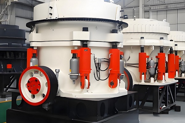
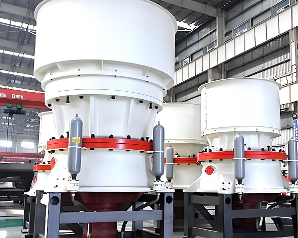
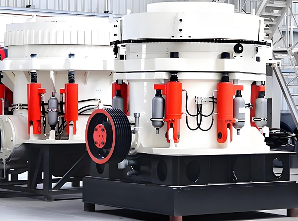
Cone crushers, core equipment for fine material crushing in industries such as mining, construction, and metallurgy, offer advantages such as high crushing ratios, uniform product particle size, and robust operational stability. They are widely used in processing hard materials such as granite, limestone, and iron ore. However, they are often subjected to harsh operating conditions characterized by high loads, strong impacts, and high dust levels. These factors can lead to various failures, such as component wear, lubrication failure, and improper operation, which directly impact production efficiency and equipment life. This article systematically examines common cone crusher failure types, analyzes their causes, and proposes targeted repair and preventative measures to provide technical support for stable equipment operation.
Core Operating Principles and High-Prone Areas of Failure in Cone Crusher
Before analyzing a fault, it's important to first understand the basic operating logic of a cone crusher: The motor drives the eccentric sleeve around the main shaft through a transmission mechanism, including a V-belt, drive shaft, and bevel gears. This drives the crushing cone in a periodic "oscillating" motion. When the crushing cone approaches the fixed cone (fixed cone), the material between them is crushed by compression, bending, and shear forces. As it moves away from the fixed cone, the crushed material falls along the cone cavity, completing the crushing cycle.
Structurally, the most common areas of failure in a cone crusher are concentrated in four core modules: the transmission system, the crushing system, the lubrication system, and the hydraulic system. Components in these modules are directly involved in force transmission, material crushing, and equipment protection. Failures in these modules can trigger a chain reaction, leading to complete machine downtime.
Common Cone Crusher Failures, Causes, and Repair Solutions
A. Unsatisfactory Crushed Product Particle Size (Too Coarse or Uneven)
1. Symptoms
After crushing, the material particle size exceeds the designed range (too coarse), or there is significant variation in the coarseness of the material within the same batch (uneven). This requires secondary crushing, increasing production costs.
2. Core Causes
Improper discharge port clearance setting: The discharge port clearance is a key parameter that determines product particle size. Too large a gap results in a coarse product, while too small a gap can easily lead to material blockage, which in turn leads to uneven particle size due to incomplete crushing.
Severe wear of the crushing cone/cone liner: Long-term crushing of hard materials can cause uniform wear or partial cracking of the liner (especially at the lower end of the crushing cone and in the middle of the cone), increasing the actual crushing chamber volume and reducing crushing force.
Uneven material feeding/overloading: Fluctuating feed rates, or a single feed rate exceeding the equipment's processing capacity, can lead to material accumulation in the crushing chamber, causing some material to be discharged before being fully squeezed, resulting in uncontrolled particle size.
3. Repair and Solutions
Adjust the discharge opening clearance: After shutting down the machine, adjust the clearance using the hydraulic adjustment device (or manual screw). Refer to the "Material Hardness Gap Correspondence Table" in the equipment manual (e.g., when crushing granite, the clearance is usually set to 1525mm, and when crushing limestone, it is set to 2030mm). After adjustment, perform a no-load test run for 5-10 minutes to check the gap stability.
Replace Worn Liners: If the liner wear exceeds 1/3 of its original thickness, or if obvious cracks or chipping occur, it should be replaced promptly. During replacement, ensure the coaxiality of the crushing cone and the fixed cone liner (tolerance ≤ 0.1mm) to avoid localized wear caused by installation deviation.
Optimize the feeding system: Install a vibrating feeder or belt scale to ensure uniform and quantitative feeding. Install grates at the feed opening to prevent large pieces of material (exceeding 1.2 times the feed opening size) from entering the crushing chamber and avoid overloading.
B. Abnormal Vibration and Noise in the Transmission System
1. Symptoms
Significant vibration (body amplitude > 0.5mm) occurs during operation, accompanied by a "buzzing" or "clicking" sound. In severe cases, this may indicate loosening of the motor base bolts or overheating of the drive shaft bearings.
2. Core Causes
Uneven transmission belt tension: V-belts become loose after long-term use, or multiple belts have inconsistent lengths, leading to slippage and skipping during transmission, causing vibration. Worn pulley grooves further exacerbate uneven belt force.
Excessive clearance between the eccentric sleeve and the main shaft: The eccentric sleeve is a core component for power transmission. Long-term high-load operation can cause the clearance between its inner wall and the main shaft to expand from an initial 0.050.1mm to over 0.3mm. This results in radial play during rotation, causing vibration throughout the entire machine. Poor bevel gear meshing: If the meshing clearance between the driving bevel gear on the drive shaft and the driven bevel gear on the eccentric sleeve is excessive during installation (normal clearance is 0.15-0.25mm), the tooth surfaces are worn, or there are foreign objects (such as metal debris), this can increase the impact during meshing, causing noise and vibration.
3. Repair and Solution
Inspect the drive belt and pulleys: Replace belts with excessive wear (if the elongation of a single belt exceeds 5%, replace the entire set). Adjust the belt tension (press the center of the belt and control the deflection to 10-15mm). If the pulley groove is worn more than 2mm, repair it by turning or replace the pulley. Repair the eccentric sleeve and main shaft mating surface: After removing the eccentric sleeve, inspect the wear between the main shaft outer diameter and the eccentric sleeve inner bore. If the wear is minor, repair the mating surface with chrome plating (thickness 0.03-0.05mm). If the wear is severe, replace the eccentric sleeve or main shaft. Apply a wear-resistant grease (such as molybdenum disulfide lithium grease) during assembly to ensure that the clearance meets the standard.
Adjust the bevel gear meshing clearance: Loosen the fixing bolts of the active bevel gear and adjust its axial position using shims to restore the meshing clearance to 0.15-0.25mm. Clean the tooth surfaces of foreign matter. If pitting or wear is observed on the tooth surfaces, polish with fine sandpaper. In severe cases, replace the gear.
C. Lubrication System Failure and Bearing Overheating
1. Symptoms
The bearing temperature exceeds 65°C (normal operating temperature 30-55°C), the lubrication station pressure gauge displays abnormal pressure (below 0.2MPa or above 0.6MPa), and the oil level gauge shows turbidity, emulsification, or metal debris.
2. Core Causes
Incorrect lubricant selection or contamination: Failure to use the specified extreme-pressure industrial gear oil (such as LCKD320 or LCKD460), or prolonged lubricant replacement (over six months), can lead to decreased oil viscosity and loss of lubrication performance. A damaged dust seal allows dust and moisture to enter the oil tank, accelerating oil contamination and clogging the oil lines with sludge.
Lubrication pump failure or oil line blockage: A damaged lubrication pump motor or worn gears can lead to insufficient oil supply pressure. Oil lines (especially those leading to bearings) can become clogged with sludge or metal debris, preventing adequate lubrication of the bearings and causing localized frictional heat generation.
Improper bearing installation or wear: Excessive interference during bearing installation (reducing internal clearance) or worn balls or cages can increase frictional resistance and generate excess heat. A damaged bearing seal can also cause lubrication failure, leading to oil leakage.
3. Repair and Solution
Replace and clean the lubrication system: Completely drain the old oil from the oil tank. Flush the oil tank, filter (if the filter element needs to be replaced), and oil lines with kerosene. Fill with new, standard lubricant, maintaining the oil level at 1/22/3 on the oil gauge. Replace the oil within one month of initial use and every six months thereafter.
Inspect the lubrication pump and oil lines: Check the lubrication pump motor wiring for proper operation and measure the motor insulation resistance (≥0.5 MΩ). Disassemble the lubrication pump and replace worn gears or seals. Purge the oil lines with compressed air (0.4 MPa) to ensure they are unobstructed.
Repair or replace bearings: After disassembling the bearings, inspect the ball bearings and raceways for scratches and pitting. If wear is minor, clean and reassemble (heat the bearings to 80-100°C during assembly to facilitate installation). If wear is severe, replace the bearings with the same model (such as SKF 23130CC/W33) and ensure the bearing clearance meets the equipment requirements (generally 0.12-0.18 mm).
D. Hydraulic System Failure (Overload Protection Failure, Discharge Port Unable to Adjust)
1. Symptoms
The hydraulic safety device fails to activate during overload, causing the crushing cone to become stuck.
When operating the hydraulic adjustment valve, the discharge port clearance remains unchanged, or it shifts after adjustment.
2. Core Causes
Hydraulic oil contamination or insufficient pressure: Impurities in the hydraulic oil can cause the relief valve and check valve spool to become stuck, preventing them from opening or closing properly. Insufficient hydraulic pump supply pressure (below the specified value of 1520 MPa) prevents the piston from adjusting the discharge port or providing overload protection.
Damaged Seals: Seals (such as O-rings and Y-rings) on hydraulic cylinders and pipe joints leak due to aging, wear, or scratches during installation, resulting in a drop in hydraulic system pressure. Worn cylinder walls can exacerbate seal damage, creating a vicious cycle. Solenoid reversing valve failure: The solenoid reversing valve coil that controls the flow of hydraulic oil has burned out, or the valve core has become stuck. This prevents hydraulic oil from entering the cylinder as directed, rendering the discharge port adjustment function inoperable.
3. Repair and Solution
Clean the hydraulic system and check the pressure: Replace the hydraulic oil (use anti-wear hydraulic oil LHM46), clean the oil tank, filter, and hydraulic valves; start the hydraulic pump and check the supply pressure using a pressure gauge. If the pressure is insufficient, adjust the relief valve pressure to the specified value. If this adjustment fails, inspect or replace the hydraulic pump.
Replace seals and repair the cylinder: Disassemble the cylinder and oil pipe joints, and replace all aged or damaged seals (fluororubber is recommended for oil and high temperature resistance). Inspect the cylinder interior. If wear depth exceeds 0.1mm, perform honing repairs (roughness Ra ≤ 0.8μm) to prevent further seal damage. Repairing the solenoid reversing valve: Measure the resistance of the reversing valve coil (normally 5080Ω). If the resistance is infinite, the coil is burned and needs to be replaced. If the coil is normal, disassemble the reversing valve, clean the valve core of impurities, apply hydraulic oil, and reassemble to ensure smooth movement.
Daily Maintenance and Preventive Measures for Cone Crusher
The key to troubleshooting is "prevention first." Through scientific routine maintenance, the failure rate can be significantly reduced and the equipment life can be extended:
1. Regular inspections and recording of key parameters: Daily inspections of equipment vibration, noise, bearing temperature, lubricant oil level and color; weekly measurements of discharge port clearance and belt tension; monthly inspections of hydraulic system pressure and seals; and maintaining an equipment maintenance log to promptly identify abnormal trends.
2. Standardized lubrication management: Strictly select lubricant types according to the equipment manual, regularly replace the lubricant and filter element, and ensure a clean lubrication system. In dusty operating conditions, install an oil-air lubrication device to improve lubrication efficiency and dust protection. 3. Control material properties and feed rate: Avoid crushing materials with high hardness (e.g., Mohs hardness > 8) or containing metallic impurities. Install an iron remover at the feed inlet if necessary. Use an automatic feeding system to control the feed rate, and strictly prohibit overloading.
4. Regular maintenance: Perform a comprehensive overhaul every 36 months, focusing on checking liner wear, transmission component clearances, and the condition of hydraulic seals. Maintain a spare parts inventory for vulnerable parts (such as liners, belts, and seals) to ensure timely replacement.
Cone crusher failures are often related to wear, contamination, and improper operation. Maintenance should adhere to the principle of "diagnosis before repair, cleaning before assembly" to avoid secondary damage caused by reckless disassembly. Furthermore, operators should prioritize operator training to ensure they understand the equipment's operating principles and basic maintenance skills. Combined with regular maintenance and fault warnings, this maximizes the performance of the cone crusher and ensures continuous and stable production.


Company: Zhengzhou ZhongCheng environmental protection equipment co., LTD

Company address: 36 xueyuan road, Zhengzhou City, Henan Province, China.

Whatsapp:+86-18738194110


Our Email

Our phone
 86-18738194110
 86-18738194110

Save Time! Get A Detailed Quotation Quickly.


 2026-04-22